D.A

Daniel Ash
Automation Engineer
About me
My name is Dan and I help make custom automated equipment come to life. In school I studied mechanical engineering and specialized in mechatronics (a fancy word for robotics). I have built off my education throughout my career to develop a specialized skillset focusing on all aspects of automated machines: PLC programming, HMI design, I/O selection and troubleshooting, electrical cabinet design, as well as validation and documentation. In my current role as an Automation Engineer at Inari Medical, I work as an internal contractor for automated equipment assisitng other departments with their automation needs. Through this I have had the opportunity to work on a wide variety of custom machines utilizing motion control, vision systems, custom graphics, presice control loops, and much more. If you think I could be a good fit for a current or future automation project, you can reach out to me through the contact form at the bottom of the page. Thank you for reading!
California Polytechnic State University - San Luis Obispo
B.S. Mechanical Engineering - 2019
Concentration: Mechatronics



Featured Projects
Automated Tipping Conveyor
[ 2023 ]
Automated Braid Angle Measurement
[ 2021 ]
Electropolish
[ 2021 ]
Molten Salt Bath
[ 2022 ]
[ 2023 | Cost: $50k | Savings: 140k/yr ]
This project was created in order to automate the bonding process of two plastic components which are part of a high-volume subassembly (~65K/yr and counting). The average time an operator took to complete the task of applying glue, pressing the parts together and curing the bond was around 1:30 - meaning it would take almost two full shifts to complete a 300 unit work order. Our machine cut that time down drastically, allowing for a syringe to be completed every 15 seconds. This allowed for the work order to get completed in only a few hours instead of two days - A 250% improvement. With this added efficiency, they can now complete 3 work orders of 300 units in a single 8hr shift with a single operator. This machine has been running issue-free in the cleanroom since July 2023.

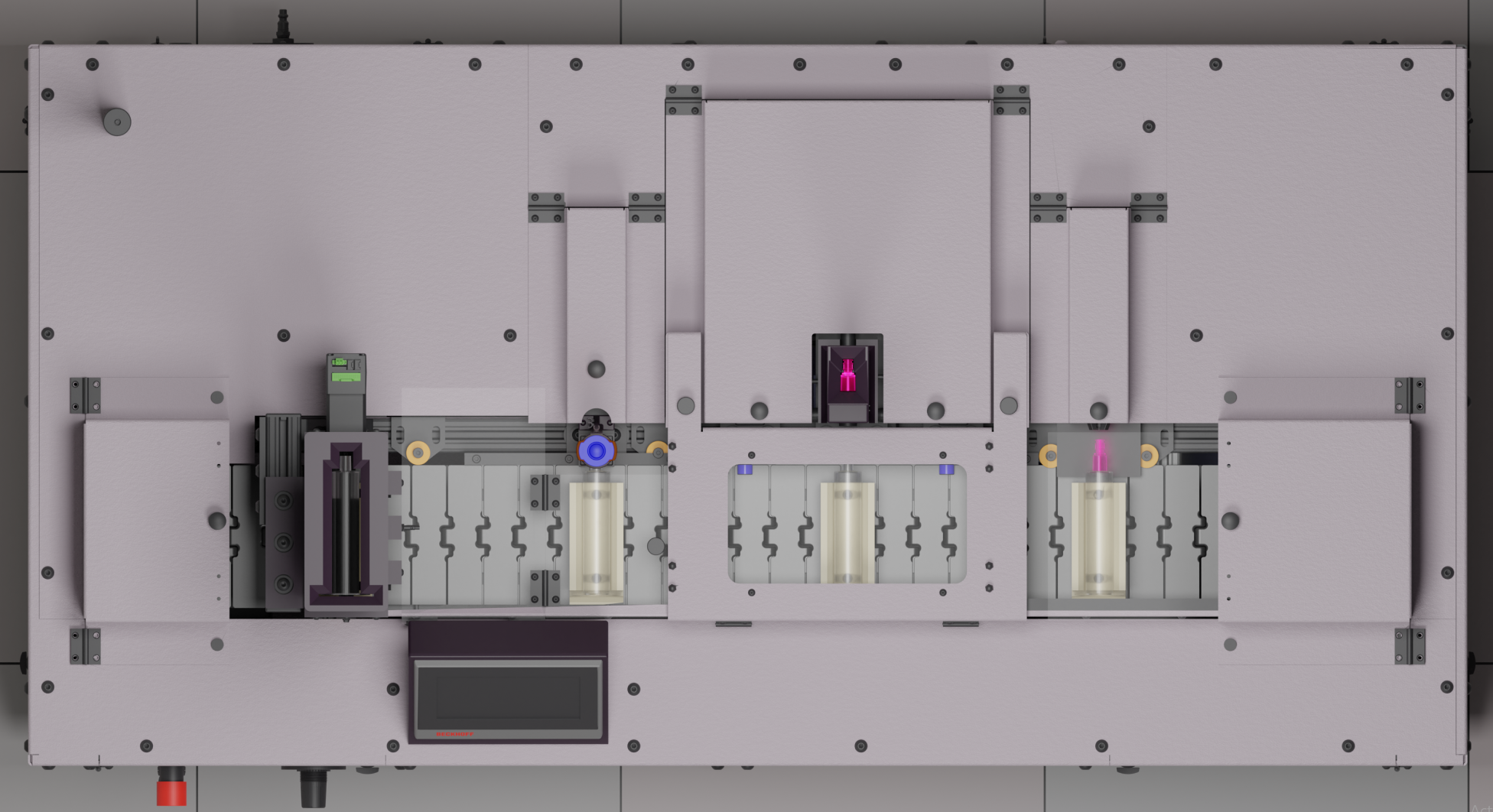
Render of machine I made for use as HMI background
This project was completed by my co-worker and I. He was in charge of the mechanical side of things and I did everything controls related. This included selecting sensors and a system which would suit our needs, along with all of the programming and human machine interface (HMI) work. This was the first project where I really got to dive into the design side of the user interface and learn how to make a beautifiul and modern looking interface that people want to use rather than the clunky and dated interfaces which are still so common on nearly all manufacturing equipment.
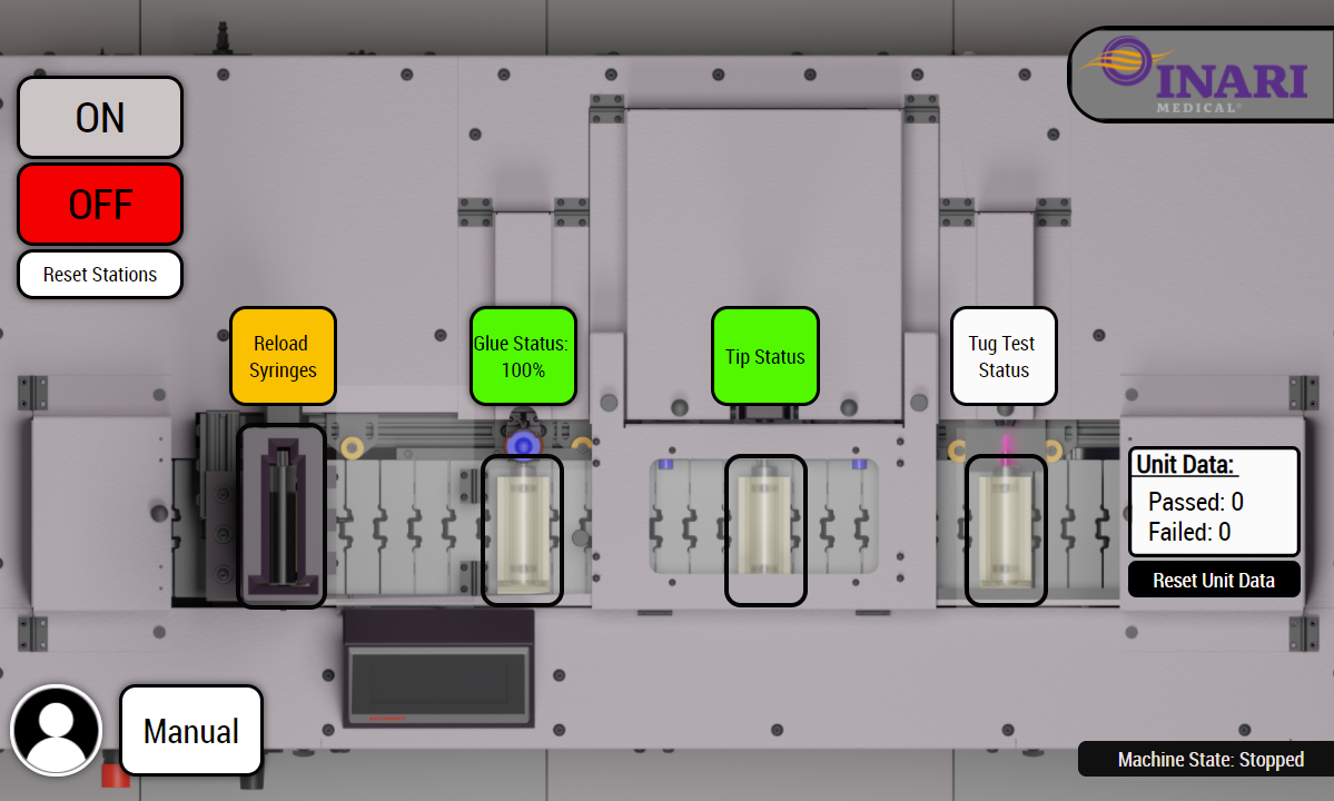
Main operator screen with content added on top of render background
Pictured above is the main operator screen for the machine. I tried to keep the interface as simple as possible so it would be intuitive to use, while also providing enough useful information. All the operator needed to do was press the "ON" button and the machine would do the rest, counting passed/failed units and alerting for any errors and prompting the user if needed as seen in the image of an example error screen below.
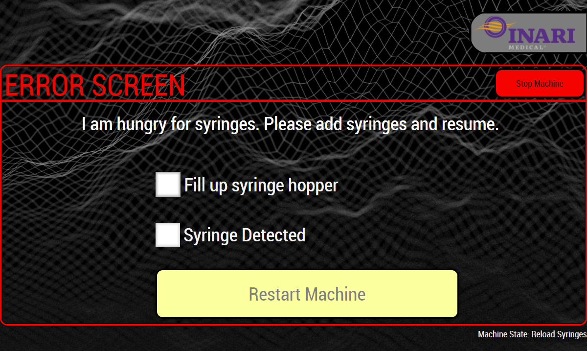
Error screen example - syringe presence
Handling the errors on this machine proved to be a bit of a challenge. There were many special scenarios which were dependent on timing and syringe locations, among other variables. For each error, this error screen would be populated with a unique error message and tasks to complete before allowing the user to restart the machine.
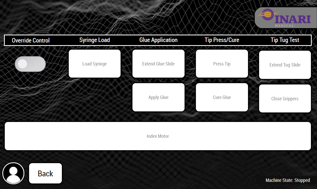
Manual operation screen
The final screen of this project is the manual operation screen. This screen is only accessable to technicians
who have a unique login which can be entered by pressing the profile button in the bottom left corner on the
main screen. This page allows the techs to set up the machine before a work order, as well as help with any
troubleshooting if there are issues with the system.
Thanks for reading! If you have any questions or would like any further information on this project or are
looking for some help with a project of your own, please feel free to reach out using the contact form at the
bottom of the page.
*Due to company policy no true images of the machine, documentation, or mechanical systems may be shown
[ 2021 | Cost: $10k ]
This fixture was given to me as a way to verify the calibration of our vertical braiding machines
automatically. This was originally planned because of issues
with braids being out of spec and ruining entire lots due to improper machine calibration.
The operation of this fixture was very simple: the mandrel with a completed braid would be placed in the locating fixture, then
the camera would automatically identify the unit and verify if the pick angle of the braid was in spec, and finally the result
would be communicated to the user through the screen.
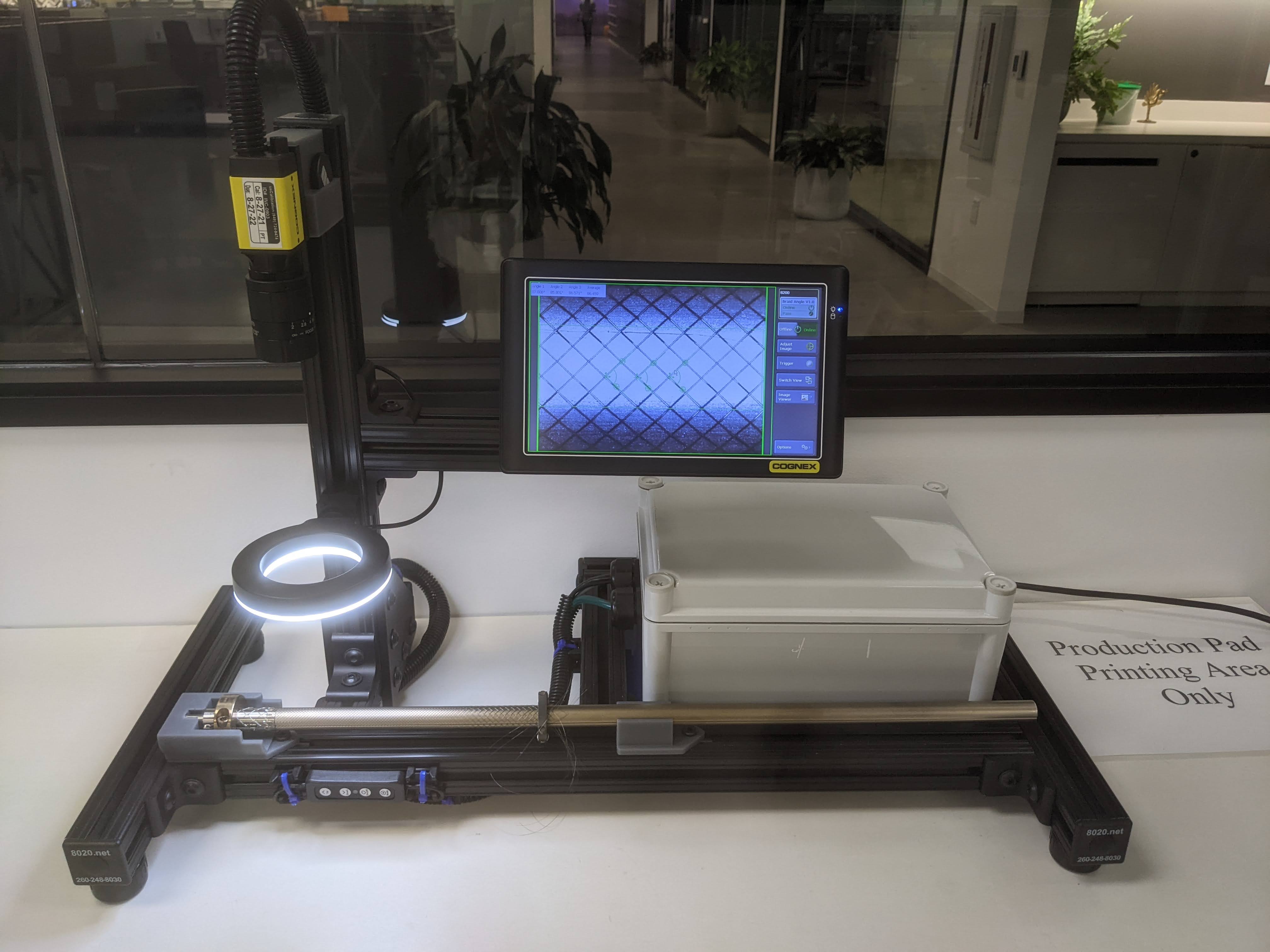
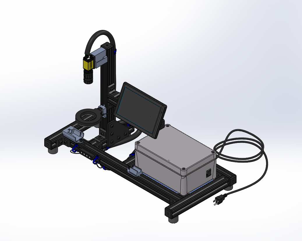
Overall image of the assembled fixture
For this project I used a Cognex In-Sight 8200 camera with In-Sight explorer to configure the software. The fixture also had a screen where the user could monitor the output of the camera. The screen also displayed the value of the 3 angles being measured and the average which the result of the test was based on.
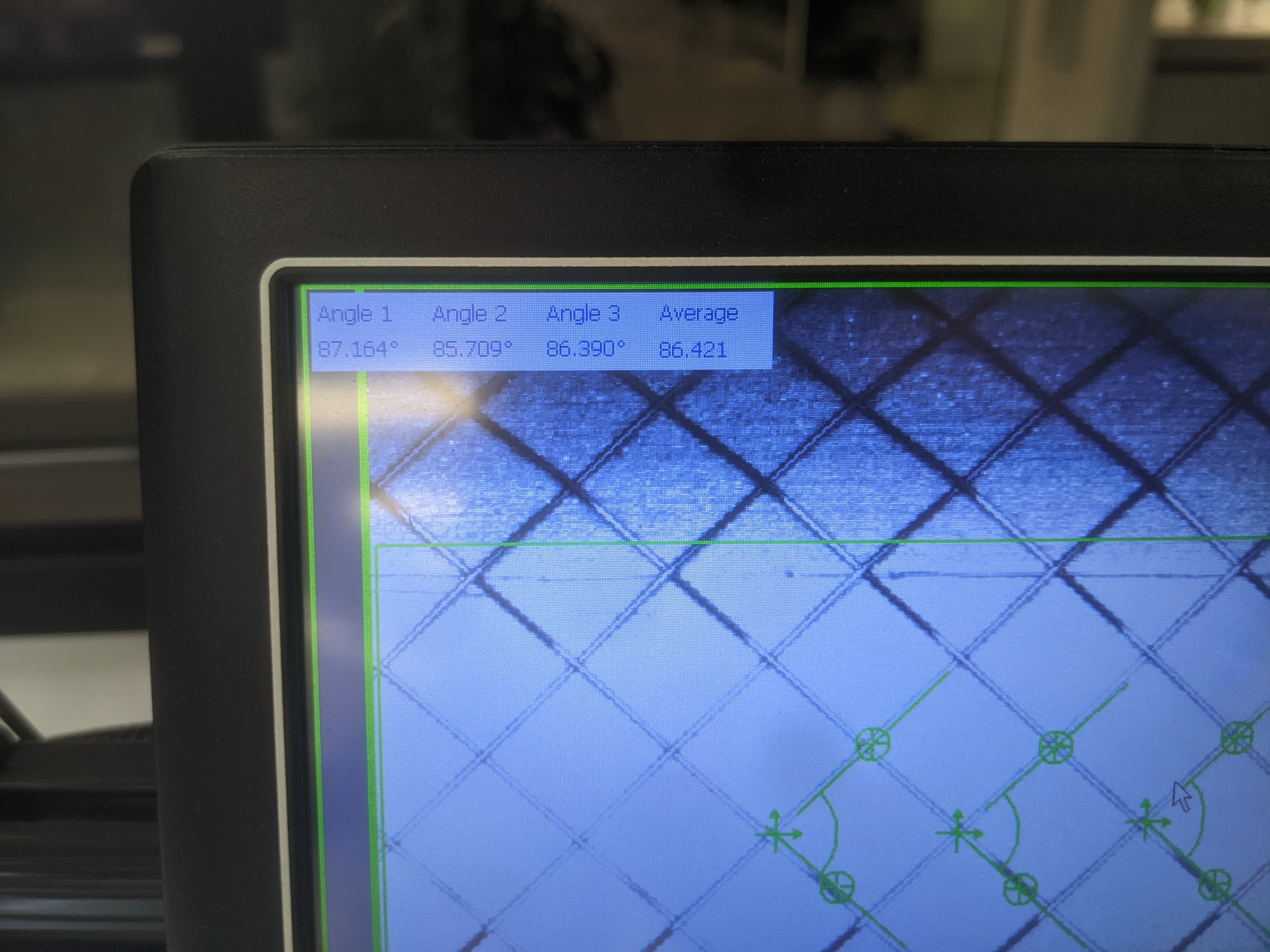
Screen of passing measurement
This photo shows what the operator would see which was the measurement of all 3 angles, along with the average.
Being one of my first builds when coming to Inari, I still had a lot more to learn (and still do). Although not the
most elegant looking solution, I was very happy with how the final project came out and how simple and painless This
tool was to use.

Overall image of the assembled fixture
For this project I used a Cognex In-Sight 8000 series camera with In-Sight explorer to configure the software. The fixture also had a screen where the user could monitor the output of the camera. The screen also displayed the value of the 3 angles being measured and the average which the result of the test was based on.

Screen of passing measurement
[ 2021 | Cost: $15k | Savings: $50K ]
For this system I worked with a senior engineer in charge
of developing nitenol processing capabilities in house, and helped build a system for electropolishing
(a chemical process for removing sharp edges). He directed me on what he needed the system to do and I
created a control system and user interface to allow him to carry on with his process development. The
main functions of the system were to allow the user to create a voltage profile which would be applied
to the component through the control of a power supply. The system was also to monitor acid temp and
store data for later review. The voltage and amperage data were also plotted vs time to give the user a
visual representation that could be reviewed - this could be seen on the "Scanning" tab.
Since this was very early on, I had not established a standard for controllers yet. Since this
application required large amounts of fast and presice data collection, we decided to go with a NI
CompactDAQ.
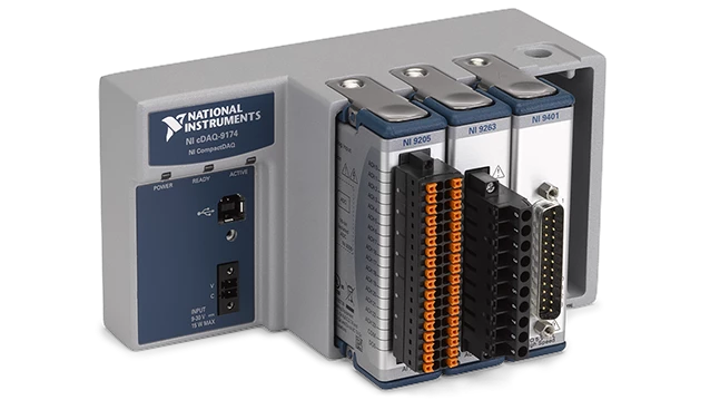
Image of NI CompactDAQ from NI website
Since this was a simple project in terms of the I/O needed, we decided to go witha 4-slot
chassis. For this machine we needed to use a 0-10v output to control the voltage and amperage limit
of the power supply, monitor the voltage/amperage using a 0-10v input, and monitor acid temp with a
thermocouple.
After selecting the controller, the next challenge was figuring out how to use the graphical
programming interface of LabVIEW.
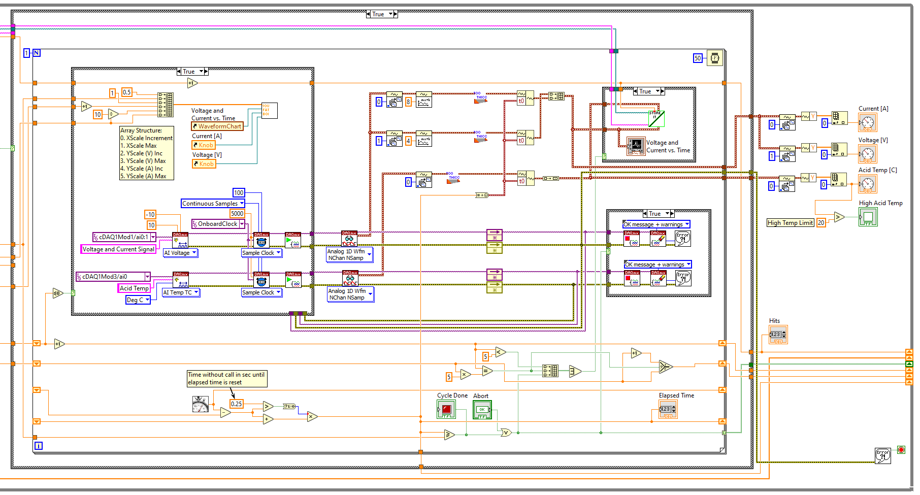
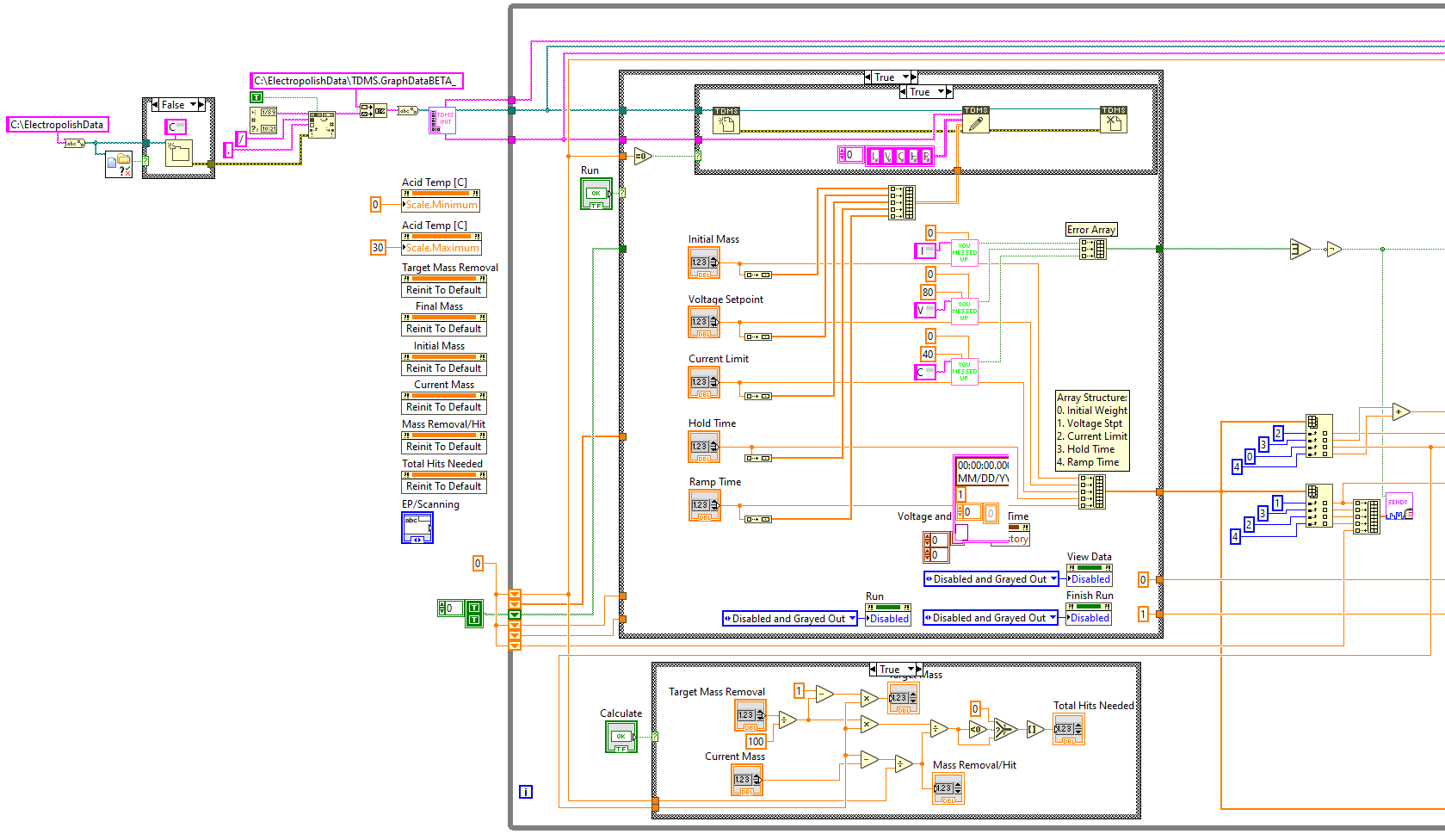
Screenshot of LabVIEW program
This image shows one small chunk of the code which I wrote for this system. It took some time to get used to the style of graphical programming but by the end I felt comfortable with it and was creating my own function blocks to keep everything organized. My overall impression of the LabVIEW environment was that it was great for data collection and creating applications with simple interfaces, but the graphical style of programming can get out of hand pretty quickly. I probably spent just as much time organizing everything to make it readable as I did with the actual programming.
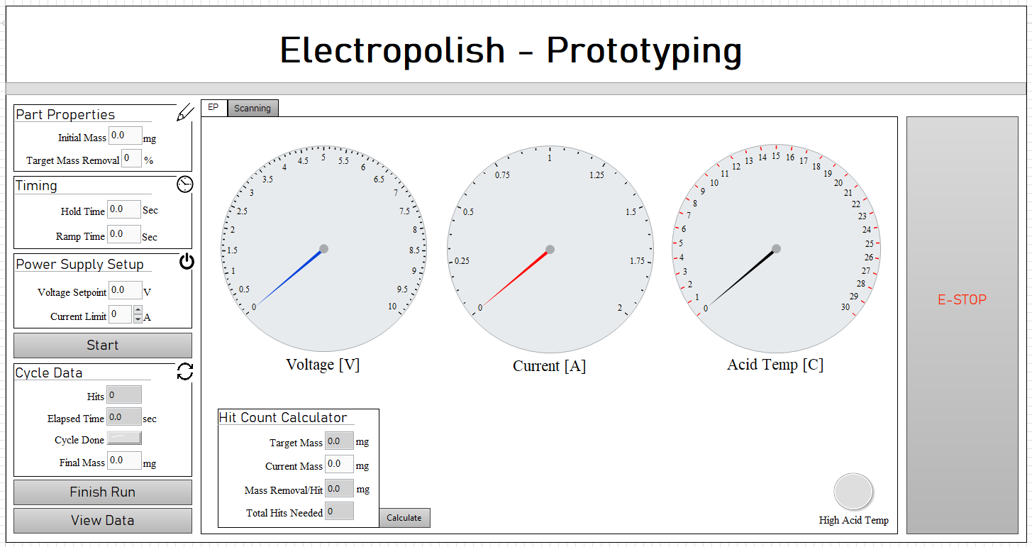
Screenshot of user interface
Lastly, this is the image of the user interface for the machine. Here the user can set up their
desired parameters and monitor machine function. The program also records and stores all voltage,
current, and acid temp data for each run for later review if necessary. There is also a "Scanning"
tab which displays a graph of voltage and curernt vs time to be used for analysis as well.
Overall this was a very successful project, saving us at least $50k on machine costs while also
keeping the technology in-house to be able to add new features as needed. This setup was key for
determining the ideal parameters for the EP process.
*Due to company policy no true images of the machine, documentation or mechanical systems may be shown
[ 2022 | Cost: $30k | Savings: $200K ]
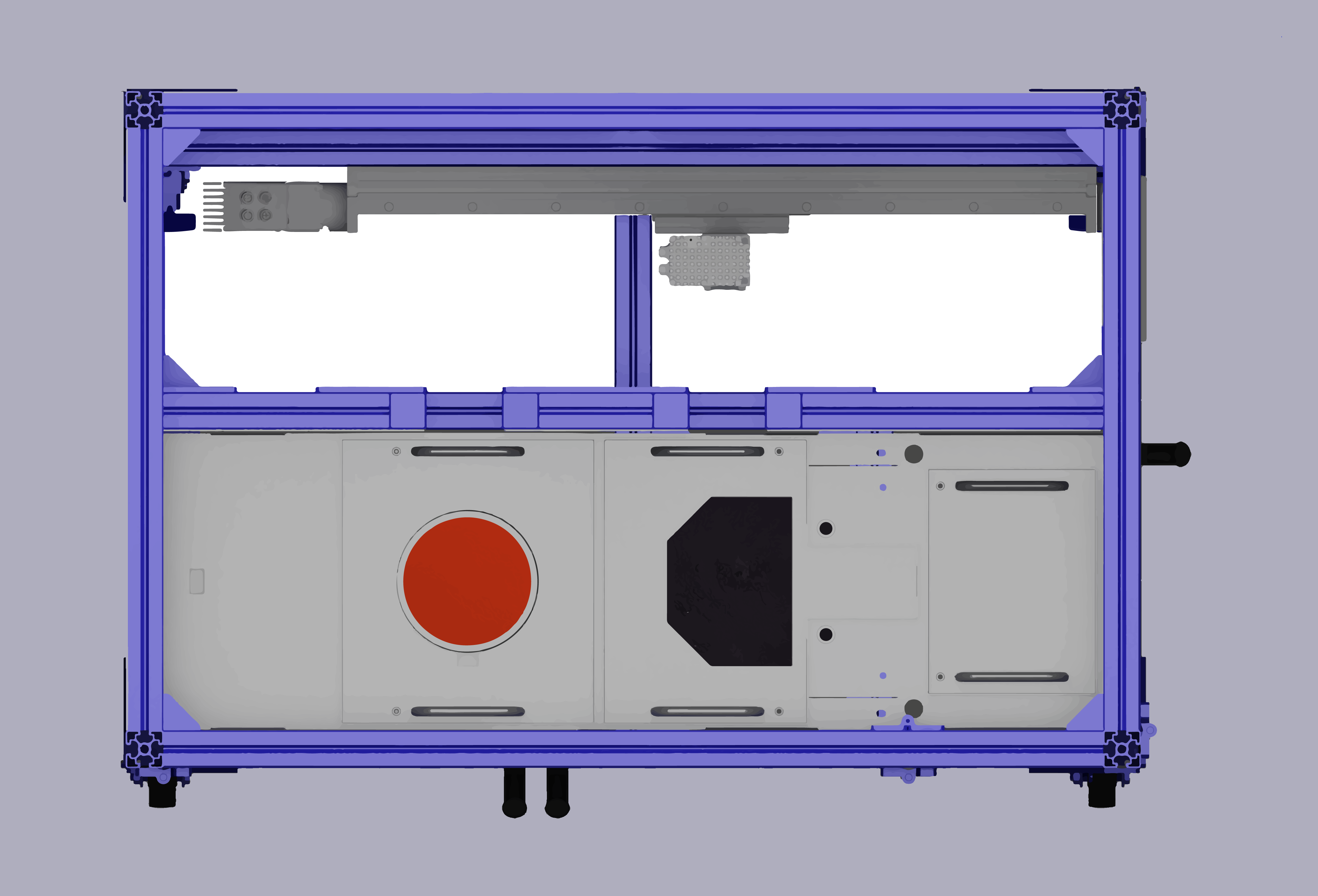
This system was created to aid in increasing nitenol processing capabilities. Initially we looked into buying a
pre-built solution but found that there weren't a lot of companies that sold salt bath machines for our scale and
the quotes we were getting on the compatable systems were north of $200k with long lead times. Because of these
reasons we decided it would be best if we built the system ourselves instead.
I led this project with a
team of about 5 other engineers and technicians, all contributing to the successful completion of this machine. My
role was the controller programming, human-machine interface (HMI), electrical panel and wiring, and overseeing the
completion of other tasks taken on by other individuals.
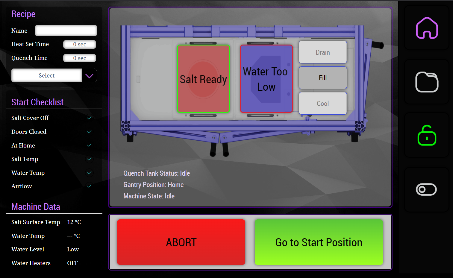
Main HMI screen
The image above shows the main screen of the HMI where the control and monitoring of the machine takes palce. The right edge of the screen shows the navigation tab where the user can go to the recipe screen, lock the doors, or turn on the "party lights" which activate the LED strip to pulse purple and orange (Inari colors) when the machine is idle. The bottom buttons allow the user to control the x-y gantry which carries a basket for components to be heat set. In the top right of the screen the user can select a recipe to use and the active recipe will be displayed. Also on the left side is all the relevant machine data and statuses taken into account before allowing a part to be heat set. In the middle of the screen there are also controls for the quenching tank as well as statuses for the state of both the salt and the quench water.
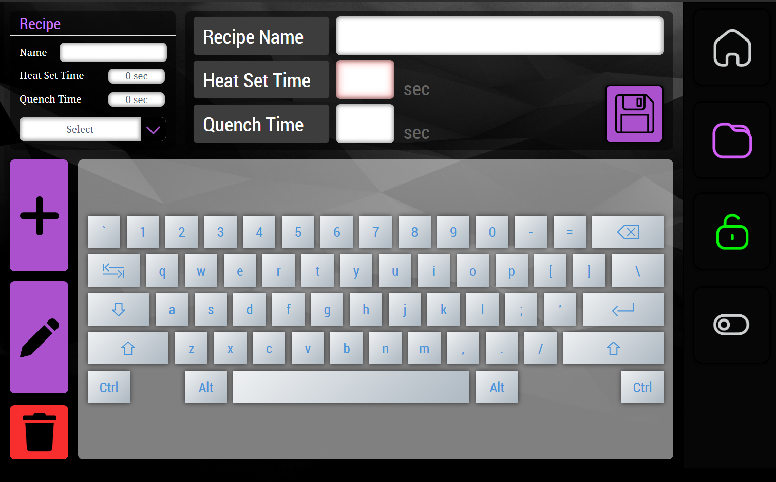
Recipe screen
Next is the recipe screen. This screen allows the user to add, edit, and delete recipes. When adding or editing recipes, the appropriate keyboard is displayed for category of data: ex. when entering a name the full keypad is available, though when entering a number only the keypad is shown. All recipes on this page are processed though a recipe function block I created for this application and have been able to reuse for future projects.
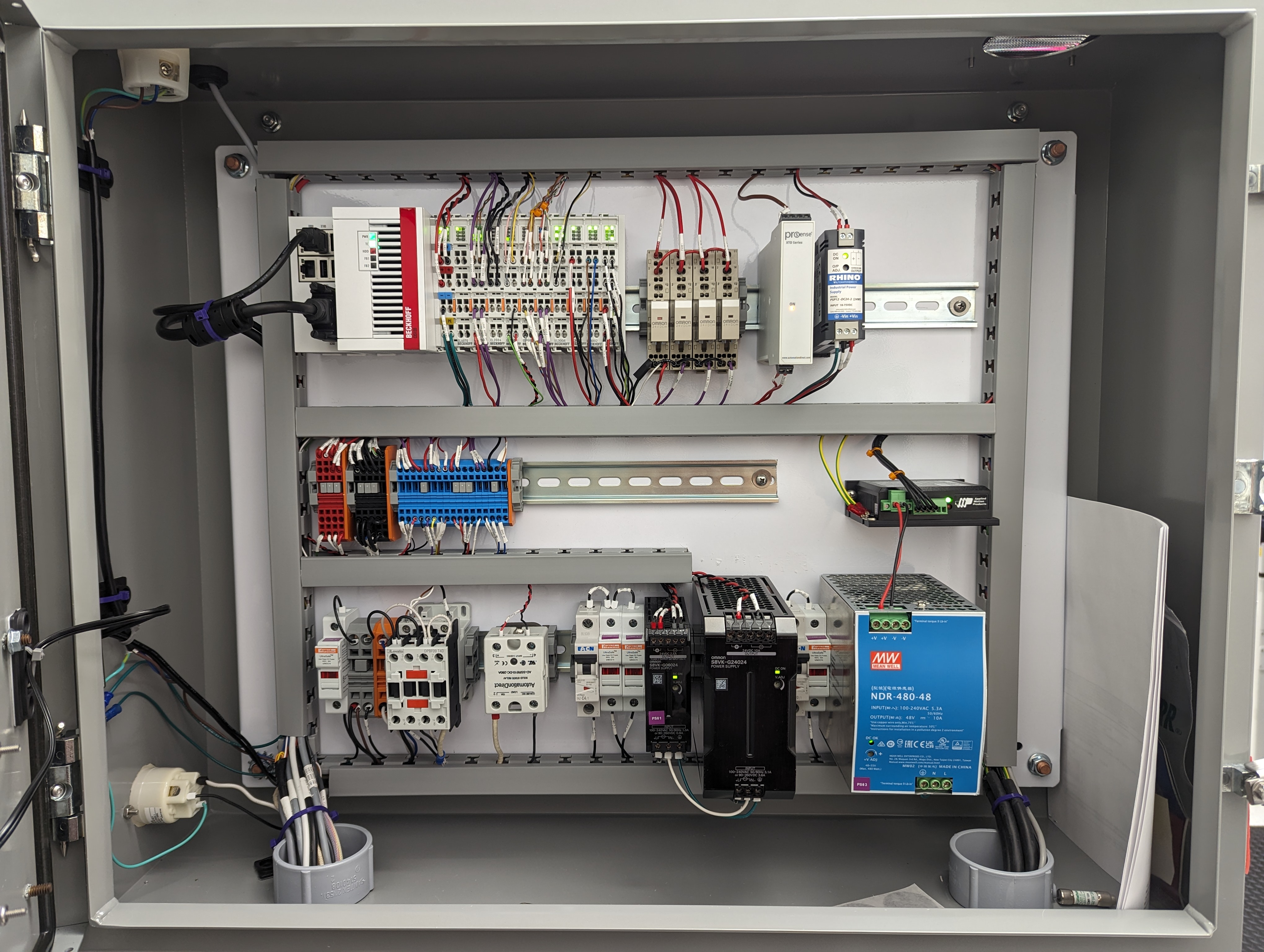
Electrical Cabinet
Pictured above is the electrical cabinet for the salt bath. The bottom row handles incoming power and everything
needing a 120v source including a relay for controlling power to the salt furnace, a solid state relay for
controlling the heater for the quenching water, and power supplies for the controller, inputs/outputs (I/O), and
motors. The middle row handles 24v power distribition and signals from I/O, as well as a regen clamp for the
motors on the far right. The top row shows the Beckhoff CX-5120 outfitted with several digital I/O terminal, a
4-20ma input terminal for a temperature sensor, and a terminal for controlling an LED strip (EL2564). I learned
on this project that wires on Beckhoff controllers should only be landed from below to avoid obstructing the
status LEDs of the terminals which I was guilty of doing this time around. Next to the controller are relays
controlling the pump and valves for the quench tank, a thermocouple to 4-20ma converter, and a DC-DC converter
for the LED strip. Congrats if you made it through this ramble.
Thanks for reading! If you have any questions or would like any further information on this project or are
looking for some help with a project of your own, please feel free to reach out using the contact form at the
bottom of the page.
*Due to company policy no true images of the machine, documentation or mechanical systems may be shown
Contact Me